|
LED Ring Light
Back when I started using
eBay to sell stuff, I suddenly needed something I didn't have - good closeup lighting. Commercial ring lights for the part-time user are way overpriced.
Professionals can afford them but what about the rest of us? The answer is to build my own.
Digital photography
offers a big advantage over film - the instantaneous feedback of exposure.
What this means is that for my ring light, I don't need fancy flash control.
I just need a device that can light the scene, and let the camera's meter
handle the rest. If the exposure looks bad, simply re-shoot.
My LED ring light consists of
two parts - a ring portion that screws onto the filter ring of a lens and the
battery portion.
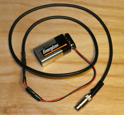
The battery section is
very simple. I started with a simple audio cable and cut it into a long
section and a short section. The long section goes with the battery. A
9v battery clip is soldered to the cable on one end and a female RCA
connector is soldered onto the other end. That's it. The picture below shows the result.
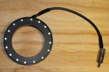
The short cable is
used to provide power to the ring light LEDs. To get enough light, I used high
brightness white LEDs. Mine came from an eBay seller from Hong Kong but you
can find them at domestic suppliers as well. I bought a pack of 50 LEDs for
$10.99 (includes overseas s&h). These are small (3mm) devices and are rated at
16000 mcd output with a color temperature of ~7000K. Forward voltage drop
is about 3.3v at 20mA. Note that these are 2005 prices.
To hold the
LEDs, I used a step-up 58-to-77mm filter ring ($7 with s&h). 58mm happens to be the filter
size of the lens I'm using. The size difference to 77mm give me enough space
to mount the LEDs. I used 16 LEDs though I had enough space for more. For
each LED, I drilled a small hole and glued the LED with some epoxy. I also
had to add some current limiting resistors. Since I'm using a 9v batttery
for power, I can use one resistor for every two LEDs and save some room on
the step-up adapter. Each pair of LEDs is wired in series (being careful to
observe polarity) with a 100 ohm resistor. All 8 pairs are then wired in parallel.
The combined power draw is about 160mA and that comes from the short cable which
terminates in a male RCA connector. Below are pictures of the front and back of
the ring.
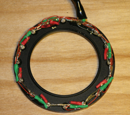
I used a
lot of epoxy to make sure the heat shrink tubing and wiring do not move
even when bumped. The epoxy also helps to stiffen the area where
the cable meets the ring since that will have the most stress in actual use.
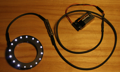
There
is no on-off switch. To use, screw the ring onto the lens and connect
the 2 cable ends. Keeping the short end short makes it a lot easier
to screw onto the lens. The cable can be an annoyance especially if
the lens has a rotating filter ring during focusing. The rotation
will drag the cord around in a circle. I typically do not screw the
unit on all the way. This gives me some play with which to rotate the
ring light thus letting the cable hang at whatever spot is convenient.
Below is a picture of the unit powered up.
|